


Document History
Version | Date | Description |
|---|---|---|
V1.0 | January 2019 | First edition |
V1.1 | December 2019 | / |
V1.2 | July 2020 | / |
V1.3 | September 2020 | / |
V1.4 | December 2020 | / |
V1.5 | December 2020 | / |
V1.6 | May 2021 | / |
V2.0 | September 2021 | Added description of USB power supply capability; |
V2.1 | May 2023 | Removed R232. Modified the quantity of USB. |
V2.2 | June 2023 | Add SRC-2000-F(S)(new Forklift version). |
V2.3 | October 2023 | Fixed some text and picture errors. Modified the Product weight and verall dimensions. Modified the Power DO and ordinary DO. Add a typical Electrical Schematic Diagram. |
Thank you for your purchase.
Only trained and qualified personnel are authorized to use this product.
It is recommended to consult the EN-1525:1997 specification for the production of mobile robots when using this product.
The use and maintenance of mobile robots produced by this product must comply with the GB T 36507-2018 Safety Code for the Use, Operation, and Maintenance of Industrial Vehicles.
Disclaimer
We have checked the contents of the document. However, we cannot guarantee that the product is exactly the same as what is described. We will regularly check the contents of the description and make necessary corrections in subsequent editing.
Technical data is subject to change without notice.
Tips:
Before using the product, please read the product manual carefully.
The controller can be disassembled only by the authorized maintenance personnel.
Before use, please fix the controller on a stable surface. Keep the controller dry and avoid overheating of the components in the chassis. Please fix the controller on a bottom plate with good heat conduction.
Before connecting the controller to the power supply, please confirm that the power supply voltage and the connection method of the power supply terminal meet the requirements.
Please put the power cord in a place where it will not be stepped on, and do not stack any objects on the power cord.
Before connecting or removing any equipment, please make sure that all power cords have been removed in advance.
Please pay attention to all the precautions and warnings mentioned in the manual.
If there is an abnormal situation during the use of the equipment, please consult a professional.
Do not place or store this device in an environment where the ambient temperature is higher than 70°C; otherwise, it will cause irreversible damage to the device.
This document cannot substitute the technical agreement. If the content in this document conflicts with the technical agreement, please refer to the technical agreement or contract.
The right of final interpretation to this document is reserved by Shanghai Seer Intelligent Technology Corporation.
1. Introduction
1.1 Product Introduction
The product is a universal controller designed for mobile robots (AGV, AMR, automatic forklifts, etc.), providing them with core features such as map building, localization and navigation and model editing. The controller is adaptable to multiple laser radars, and provides rich interfaces of I/O, CAN and RS485 for accessing various sensors and drivers. The product integrates the core components of mobile robots, combined with powerful client software, to help users quickly complete their manufacturing and application.
This product is developed and manufactured under license by Shanghai Sengong Intelligent Technology Co., LTD. © All rights reserved.
Trademark
Some of the names below and possibly other names without the registered trademark symbol ® are registered trademarks of Shanghai Seer Intelligent Technology Corporation:
仙工, SEER and SRC
It has been certified by CE and conforms to EN 61010-1:2010, CE-EMC (IEC 61326-1) standards.
1.2 Overview of Functions
Power ON Mode | Provides a one-key system power ON/OFF interface |
|---|---|
Digital Input | Provides 11 digital input interfaces (the old version provides 9 channels) |
Power Digital Output | Provides 8 controllable power digital output interfaces (the old version provides 7 channels) |
Ordinary Digital output | Provides 2 ordinary DO interfaces (the old version has no ordinary digital output) |
Battery Management | Provides corresponding battery switch management ports for batteries with output switches |
Fault Alarm | Provides a port for indicating alarm status |
Emergency Stop Forwarding | Provides a feature of forwarding one emergency stop input to two emergency stop outputs |
Electromagnetic Braking | Provides 2A electromagnetic brake release output |
Communication Bus | Provides a variety of communication bus interfaces such as RS485, CAN and USB |
Posture sensing | The built-in six-axis acceleration sensor accurately senses the posture of the controller |
Temperature & humidity environment | The built-in temperature and humidity sensor effectively senses the environment inside the controller |
Network Interface | Integrates six-port Gigabit network switch and 2.4/5GHz dual-band Wifi (non-industrial) |
1.3 Product Dimensions and Environment
Dimensions: 225.2 x 128 x 83.8 mm
Weight: 1.5 kg
Operating Temperature: 0 ℃ to 50 ℃
Operating Humidity: 10% to 90% Relative Humidity, No Condensation
Storage Temperature: -20 ℃ to 60 ℃
Protection Level: IP42
1.4 Requirements for External Power Supply
Overall Specification | The machine is powered by batteries. The batteries have two common specifications: 24 V and 48 V. The controller needs to provide stable 24 V power through a regulated power supply or a voltage regulator module. |
|---|---|
Voltage | 24 V (±10%) |
Ripple and Noise | 150 mVpp |
Machine Power | 48 W (excluding Power DO load) |
2. Dimensions and Installation
2.1 Appearance and Dimension Drawing
SRC-2000 can meet different application requirements such as industrial AGV (AMR), commercial AGV (AMR), and automatic forklift.
Model | SRC-2000-I(S) | SRC-2000-F(S) |
|---|---|---|
Application Field | Industrial AGV (AMR) | Automatic forklift |
Color | Black | Dark Grey(metal housing) |
Unit: mm

SRC-2000-I(S)


SRC-2000-F(S)
2.2 Installation Precautions
2.2.1 Installation Direction
The mounting surface of the fixed base plate of the controller must be perpendicular to any direction of the space coordinate system.
Allowable placement directions (where X, Y, Z are the directions of the space coordinate system
Wrong placement directions (where X, Y, Z are the directions of the space coordinate system):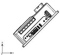


2.2.2 Coordinate Direction of Gyroscope


SRC-2000-I(S)


SRC-2000-F(S)
2.2.3 Mounting Holes
Unit: mm

The red one is the size of the mounting hole of the controller.
The blue one is the size of the mounting screw via of the controller (M4 locking screws are recommended)
The mounting holes position of SRC-2000-I(S) and SRC-2000-F(S) are same.
Notes:
It is recommended that the mounting surface of the controller have a certain capacity of heat dissipation to accelerate the controller's heat radiation and ensure its operating performance.
There are two grounding holes on the right side of the controller, either of which connects the controller to the robot body through the Y-shaped or O-shaped terminal.
2.2.4 Reserved Space for Wiring

The wiring reserved space is same for SRC-2000-I(S) and SRC-2000-F(S).
3. Interfaces and General Functions
The table below summarizes the number of external ports on the controller:
The following table provides an overview of the controller's external interfaces and quantities:
NOTES:The "new version" below refers to the controller with hardware version h1-2-10 or up.
Controller models | SRC-2000-I(S) / SRC-2000-F(S) | |
|---|---|---|
Old version | New version | |
Communication interface | ||
CAN | 2 | 2 |
RS485 | 3 | 3 |
RS485 used for battery communication | 1 | 1 |
USB2.0 | 2 | 0 |
USB3.0 | 2 | 4 |
Control Interface | ||
Power DO (maximum single output current is 2 A, DO_0-7) | 7 | 8 |
Ordinary DO (maximum single output current is 400 mA, DO_8-9) | 0 | 2 |
Driver power input interface (24 V or 48 V / 10 A) | 2 | 2 |
Driver power output interface (24 V or 48 V / 10 A) | 2 | 2 |
DI (NPN) | 9 | 11 |
Emergency stop input | 1 | 1 |
Emergency stop output | 2 | 2 |
Brake release switch input | 1 | 1 (shared with DI 9) |
Power-off brake release output | 1 | 1 (shared with DO 7) |
Power On/Off button | 1 | 1 |
Network interface | ||
Wired network interface (Gigabit) | 6 | 6 |
External network interface (for extended Wifi clients) | 1 | 1 |
Wireless network interface 2.4/5GHz dual-band Wifi (non-industrial) | 1 | 1 |
Battery interface | ||
Battery switch | 2 | 2 |
Charging signal | 2 | 2 (Automatic charging signal and DI 10 are shared) |
Power interface | ||
Input voltage | 24 V / 150 mVpp | 24 V / 150 mVpp |
Input current (system operating current, excluding Power DO)) | >2 A | >2 A |
Audio and video interface | ||
Standard HDMI port | 2 | 2 |
Multimedia audio output | 1 | 1 |
Microphone input | 1 | 1 |
Indicator interface | ||
Work indicator | 1 | 1 (200 mA,Over current can cause abnormal shutdown) |
Emergency stop indicator | 1 | 1 (shared with Power DO 8, output cuernrt: 400 mA) |
Alarm lamp | 1 | 1 (shared with Power DO 9, output cuernrt: 400 mA) |
3.1 Interface Definition
3.1.1 Definition of Controller Top Interface
The interface layout is as follows: 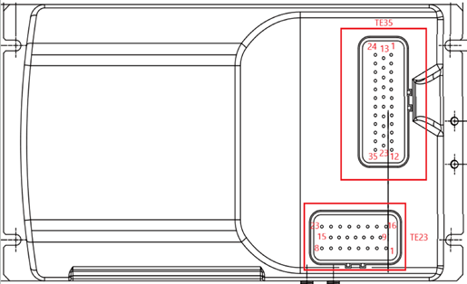
Detailed interface definition:
TE35:
[12] Alarm lamp/Power output 9 | [23] Battery switch 2N | [35] Power output 5 |
|---|---|---|
[11] Digital input 3 | [22] Battery switch 2O | [34] The power output 0 |
[10] Power output 6 | [21] Power ON lamp | [33] CAN communicate 1H |
[9] Emergency stop output 2- | [20] Mode 1 Power on | [32] CAN communicate 1L |
[8] Emergency stop output 2+ | [19] Battery switch 1O | [31] CAN communicate 2H |
[7] Emergency stop light/power output 8 | [18] Battery switch 1N | [30] CAN communicate 2L |
[6] Emergency stop switch | [17] 485 Communication 1B | [29] 485 Communication 1A |
[5] Emergency stop output 1+ | [16] 485 communication 5B(Battery communication) | [28] 485 communication 5A (Battery communication) |
[4] Emergency stop output 1- | [15] Automatic charging switch/Digital input 10 | [27] Manual charging switch |
[3] Ground | [14] Ground | [26] Ground |
[2] Ground | [13] 24V input + | [25] Ground |
[1] 24V input + | [24] 24V input + |
TE23:
[8] Digital input 4 | [15] Release output/Power output 7 | [23] Power output 1 |
|---|---|---|
[7] Digital input 5 | [14] Ground | [22] Power output 4 |
[6] Digital input 2 | [13] Ground | [21] Power output 2 |
[5] Digital input 6 | [12] Digital input 7 | [20] Power output 3 |
[4] 485 communication 3A | [11] Digital input 8 | [19] Digital input 1 |
[3] 485 Communication 3B | [10] Ground | [18] Digital input 0 |
[2] 485 Communication 4B | [9] Ground | [17] Release switch/Digital input 9 |
[1] 485 Communication 4A | [16] Ground |
Note:
Do not bend or damage the internal pins of the connector.
Please use the connector socket and pins delivered in the package to make the wiring harness according to the connector and cable definition documents. For use with the controller, please contact SEER for the cableroller definition document.
3.1.2 Side Interface Definition
Interface Picture: 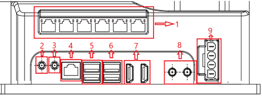
Detailed Interface Definition:
NO. | Interface Definition |
|---|---|
1 | Gigabit switch RJ45*6 |
2 | Multimedia audio output |
3 | Microphone input |
4 | RJ45 (for extended Wifi client, refer to 3.2.10 for details) |
5 | USB3.0 * 2 |
6 | USB3.0 * 2 |
7 | HDMI*2 |
8 | Wifi antenna * 2 (non-industrial); if the controller needs to connect to the wireless local area network, both antennas must be connected at the same time (extension cable can be used), and cannot be surrounded by a metal casing. |
9 | Drive power supply interfaces from top to bottom: BAT-IN1, Drive-PWR-OUT1, BAT-IN2, Drive-PWR-OUT2 |
Power supply capacity of USB:
A single USB3.0 provides 0.9 A, 3.6 A in total.
If it is a single USB device, try to plug it into the USB3.0 interface first.
The recommended connection method is as follows:
USB3.0 | USB3.0 | |
|---|---|---|
Top | USB transfer to RS485 | |
Button | speaker | Percipio camera |
3.2 Function Description of Interfaces
3.2.1 Communication interface
SRC-2000 series controllers provide two standard CAN interfaces, Four standard RS485 interfaces, four USB3.0 interfaces.
To adapt to different equipment, CAN interface and all RS485 interfaces can be configured with an internal 120ohm terminal resistor by software. The controller has a 120ohm terminal resistor by default. The 120ohm terminal resistor can be disconnected by software according to the actual service. The CAN interface is generally used to connect motor drivers, and the RS485 interface is generally used to connect ambient lamps, two-dimensional code cameras, and so on.
One dedicated RS485 interface is specially used for connecting the battery communication port. Use the communication feature after correctly wiring according to the TE35 and TE23 wire sequence definitions in 3.1.1.
3.2.2 DO interface
SRC-2000 series controllers provide 8 (the old version provides 7 channels) Power DO interfaces, which can provide 24V power for external equipment,and 2 ordinary DO interfaces.
Control the DO switchs through the software according to the actual service.
The maximum single output current of Power DO is 2 A ,and the maximum single output current of ordinary DO 8 and DO 9 is 400 mA in the new version. Total output current depends on the output current of the external power supply of the controller. The total power consumption cannot exceed 120 W (24 V / 5 A).
When Power DO is connected to inductive loads such as relays and contactors, a freewheeling diode needs to be added to the relay or contactor to eliminate the interference of the back-EMF generated on the system circuit when the inductive load is disconnected. For the connection method of the freewheeling diode, refer to Appendix 2 FAQ for SRC- 2000.
When Power DO is connected to inductive loads such as relays and contactors, a freewheeling diode needs to be added to the relay or contactor to eliminate the interference of the back-EMF generated on the system circuit when the inductive load is disconnected. For the connection method of the freewheeling diode, refer to Appendix 2 FAQ for SRC- 2000.
3.2.3 Power supply interface of external driver
SRC-2000 series controllers provide two driver power supply interfaces, each of which can carry a maximum current of 10 A.
The input interfaces BAT-IN1 and BAT-IN2 are connected to the positive terminal of the battery.
The output interfaces Drive-PWR-OUT1 and Drive-PWR-OUT2 are respectively connected to the positive poles of the two driver power input ports.
The negative pole of the power input of the driver is directly connected to the negative pole of the battery output.
After the controller is powered off, the power supply output of the driver will be turned off. When the controller is working normally, the power supply of the driver can be turned off by software as required.
Use after correctly wiring according to the interface definition in 3.1.2-9, and select the appropriate wire according to the actual current used.
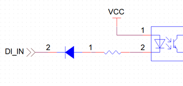
3.2.4 DI interface
SRC-2000 series controllers provide 9 (the new version provides 11 channels) DI interfaces.
DI supports 24 V input logic.
DI only supports NPN logic. It does not support PNP logic. When DI is suspended or pulled high, the controller receives high-level logic (do not connect directly to the power supply). When DI is pulled low or to the ground, the controller receives low-level logic.
Use the DI feature after correctly wiring according to the TE35 and TE23 wire sequence definitions in 3.1.1.
The internal electrical logic diagram of DI interface is as follows:
3.2.5 Emergency stop interface
SRC-2000 series controllers provide one emergency stop switch with normally closed logic, and forward two emergency stop outputs with normally closed logic.
Emergency stop switch connection: a pair of normally closed contacts, which are connected to the "emergency stop switch" and ground respectively, and one 24V emergency stop indicator, which is connected to the "emergency stop lamp" and ground respectively. Emergency stop lamp and Power DO 8 multiplexed.
The emergency stop output is generally connected to the driver's I/O port as an emergency stop signal input to the driver. The emergency stop output is a pair of dry contact switches. The maximum allowable passing current of the switch is 120 mA. Overload use will cause damage to the switch.
Use the emergency stop feature after correctly wiring according to the TE35 wire sequence definitions in 3.1.1. SRC-2000 User guide V2.3 Shanghai Seer Intelligent Technology Corporation. 17
The schematic diagram of input circuit and output circuit is shown below:


3.2.6 Power-off brake release interface
SRC-2000 series controllers provide a brake release switch input and a electromagnetic power-off brake release output interface.
The total output capacity of the electromagnetic power-off brake-driven brake release output interface is 24 V / 2 A, which can be expanded into four single 24 V / 500 mA brake release outputs.
Brake release switch connection: select a normally closed contacts, which are connected to the “brake release switch” and ground respectively; select a normally open battery switch contact, which are connected to the "battery switch 2N" and "battery switch 2O" respectively.
In case of power failure of the machine, if you want to move the robot, you need to press the brake release switch. At this time, the battery switch is closed to supply power to the robot, and at the same time, the electromagnetic power-off brake supplies power to the robot motor to release the brake.
Use the power-off brake release feature after correctly wiring according to the TE23 wire sequence definitions in 3.1.1.
The new version does not support the brake release function after power off, and the corresponding pin is converted to DI9 and Power DO7.
3.2.7 Power ON/OFF interface
SRC-2000 series controllers provides a interface for power ON/OFF button.
Power ON button connection: select a normally closed contact, which are connected to "Mode 1 Power ON" and ground; select a normally open battery switch contact, which are connected to "Battery switch 2N" and "Battery switch 2O"; select a 24 V power ON indicator, which are connected to the "Power ON lamp" and ground. Do not use switch sharing normally closed and normally open contacts. Do not use switch with self-locking, for more details please refer to Appendix 2-1.
Power ON: Press and hold the power ON/OFF button until the power ON indicator is on, then release the power ON button to complete the power ON process. Power OFF: Press and hold the power ON/OFF button for 2 seconds and then release it, wait a few seconds for the power ON indicator to go out and complete the power OFF process.
Use the power ON/OFF feature after correctly wiring according to the TE35 wire sequence definitions in 3.1.1.
3.2.8 Battery switch and charging signal interface
SRC-2000 series controllers provide another battery switch interface, "Battery Switch 1N" and "Battery Switch 1O", which are connected to the switch control interface on the battery.
The controller provides two charging switch signal interfaces, which are respectively connected to the manual charging port and the automatic charging port. When the robot is not charged, the two charging signal interfaces are suspended; when the robot is connected to the manual charger or automatic charger, the corresponding charging switch signals are SRC-2000 User guide V2.3 Shanghai Seer Intelligent Technology Corporation. 19 connected to ground, and the controller receives the charging signal. New version of automatic charging switch signal and digital input 10 multiplexing.
When the battery has a switch and requires SRC-2000 to control ON/OFF, the battery switch needs to be connected to the battery switch interface of the controller. When the battery does not have a switch, or the controller is not required to control the battery ON/OFF, the battery switch interface of the controller can be suspended.
Use the battery switch and charging interface feature after correctly wiring according to the TE35 wire sequence definitions in 3.1.1.
The internal logic diagram of two pairs of battery switches is as follows:


3.2.9 Power interface
The power supply voltage of the SRC-2000 series controller is 24 V, which is powered by an external DCDC, the ripple requirement is ≤150 mVpp, and the minimum working current of the system is 2 A (excluding the power supply requirements of Power DO).
According to the requirements of the external Power DO output current, select a DCDC power supply with appropriate load capacity.
Do not share a DCDC power supply with any motor equipment or high-power consumption equipment.
Connect the power supply correctly according to the TE35 line sequence definition in 3.1.1. Do not connect the positive and negative poles reversely.
3.2.10 External Ethernet interface
The built-in 2.4/5GHz dual-band Wifi of the controller is a non-industrial Wifi, which cannot provide industrial performance and stability.
It is recommended to use an industrial-grade Wifi client to ensure a stable Wifi connection and t o achieve roaming among multiple APs.
The wireless feature is enabled just by connecting the external Ethernet interface 3.1.2-4 to the LAN port of the Wifi client via a network cable.
Common Wifi client models include Moxa AWK-1137C ,TP-LINK TL-CPE1300D and SIEMENS SCALANCE W734-1, etc.
4. Precautions
Please be sure to follow the requirements below; otherwise, it will affect safety or cause damage to the controller:
For safety, please be sure to use a battery with short-circuit protection; if you are not sure about that, please add an air switch at the battery output;
In order to reduce the impact during power on, the controller's aluminum plate must share the ground with the battery negative terminal; specifically, the controller's aluminum plate can be connected to the battery negative terminal with a wire, or the battery negative terminal can be connected to the nearby robot body, and the controller can be connected to the nearby robot body. The two are connected through the robot body.
Please insulate all exposed terminals (bare wires on the switch).
For CAN bus, the controller is daisy-chained to connect two drivers. The controller needs to be connected to the 120ohm terminal resistor, and the driver at the far end of the daisy chain needs to be connected to the 120ohm terminal resistor. CAN cable needs to be twisted.
It is prohibited to enter the controller system to install other software programs; otherwise, it will cause unpredictable errors.
It is prohibited to modify the IP address of the controller or other internal settings; otherwise, it will cause serious communication errors.
It is prohibited to plug and unplug the TE35 and TE23 ports when the power supply is on. Pay special attention to the situation that the battery is not controlled by the controller. Make sure to plug and unplug the TE35 and TE23 ports after the battery is turned off. Otherwise, the controller may be damaged.
When the TE35 and TE23 cables are inserted into the corresponding ports, there will be a snapping sound. If you do not hear it, please inspect whether the rubber seals in the TE35 and TE23 cable connectors are turned over or curled. If so, please straighten it out, and then insert into the corresponding port.
To stop the device, please press the stop button, but do not turn off the battery directly; otherwise, it is easy to cause the hardware or software of the controller to malfunction.
If the battery is improperly replaced, it may explode. Please be sure to use the battery that is of same type or equivalent type and is recommended by the manufacturer.
The used batteries and used controllers shall be disposed of by the product purchaser in accordance with relevant national laws and regulations.
It is recommended to perform the first power-on test in the following steps:
Inspect whether the terminal block is well grounded;
Inspect whether the positive and negative poles of the terminal block are reversed;
Inspect whether the controller is well grounded;
Inspect whether the positive pole of DCDC input terminal is shorted to ground;
Inspect whether the positive pole of DCDC output terminal is shorted to ground;
Inspect whether the positive pole of the motor power supply is short-circuited to the ground;
Inspect whether the positive and negative poles of the motor power supply are reversed;
Inspect whether the positive pole of the laser power supply is shorted to the ground;
Inspect whether the positive and negative poles of the laser power supply are reversed;
Before powering on for the first time, disconnect the laser power supply and the power supply of the motor driver;
If there is no abnormality when the power is on, turn on the power supply of the motor driver after stopping the device;
If there is no abnormality when the power is on, turn on the laser power supply after stopping the device;
Start the commissioning test.
Appendix 1: Typical Electrical Schematic Diagram
If different motors and drivers are used, the wiring may be slightly different; therefore, the following figure is for reference only.


Appendix 2: FAQ for SRC-2000
1. How to connect the power ON/OFF button?
The button must be without self-locking; C1 and C2 are not connected. The number below is the line sequence of the TE35 interface.
NC: Normal Close
NO: Normal Open
C: Common
LED: Indicator Lamp
GND: Ground

2. What will happen if you press on the power ON/OFF button?
Firmware versions prior to 1.8.49:
In the power-off state: hold the button to turn on the system, then the motherboard will power off after a few seconds, while the I/O board will not power off. This situation is abnormal;
In the power-on state: if you hold the button, the system will turn off normally;
Firmware versions 1.9.0 and later:
In the power-off state, hold the but ton to turn on the system. If you do not release the key, the power-on state will be kept. If you release the key, the system will turn off in a few seconds; In the power-on state, hold the button to keep the power-on state. If you release the key, the system will turn off normally;
If the power-on button cable is disconnected, the battery will be powered again and the system will turn on abnormally, because the power-on button is pressed and held if the power ON button cable is disconnected.
3. What should we do if the controller crashes?
Press on the power ON/OFF button for more than 2s, and then release it; the controller will be forced stop.
4. How will the delayed battery output affect the start after the battery switch is turned on?
If the battery switch of the controller is used to control the external power supply and disconnect the external power supply from the battery, and the power output has a delay after the battery switch is turned on, you need to press on the power button for a longer time than the battery delay output time.
5. How to connect inductive loads such as relays and contactors etc. to PDO?
Inductive loads such as relays and contactors etc. must be connected with a freewheeling diode to eliminate the interference of the back electromotive force generated when the inductive load is disconnected on the system circuit. The cathode of the freewheeling diode is connected to the PDO output, and the anode is connected to the PDO ground.
If the freewheeling diode is not added, the possible interference hazards are as follows:

The laser communication is disturbed, and the controller may alarm about laser connection failure.
The laser communication is disturbed, and the controller may alarm about laser connection failure.
Neither 192.168.192.4 nor 192.168.192.5 can communicate.
When connecting the contactor, please judge the internal resistance and the tripping current of the contactor coil, and do not exceed the output current of the PDO (2 A).
Recommended diode model: SR3100.
6. How to activate after battery over-discharge or short-circuit protection?
The following content is only for batteries that have been verified by us to support reactivation. After the battery is over-discharged, it will enter the over-discharge protection state. At this time, even if the battery switch is turned on, the battery will not output. In this case, the battery can be reactivated in the forced charging mode of the charger; after the battery
output is accidentally short-circuited, the battery will enter the short-circuit protection state. After the external short-circuit state is cancelled, the battery should activate the forced charging mode of the charger to resume normal output.
If the forced charging activation is invalid, the battery must be returned to the factory for repair.
Appendix 3: Terms and Definitions
Terms | Definitions |
|---|---|
SRC | Seer Intelligent Robotics Controller |
AGV | Automated Guided Vehicle |
AMR | Autonomous Mobile Robot |
TE | TE Connectivity |
DI | Digital Input |
Power DO | Power Digital Output (High-level Output Supply Voltage) |
RJ45 | Eight-core Ethernet twisted pair socket |
RS232 | Asynchronous transmission standard interface |
RS485 | Differential asynchronous transmission standard interface |
CAN | Controller area network |
Roboshop | Seer Intelligent Robot Client Software |
For further details, kindly visit our official website: https://www.seer-group.com/
For API-related information, please refer to our smart documentation website: https://docs.seer-group.com


 Thanks feedback
 Thanks feedback
 Build your own AMR fleet within days


